Camera mounting and configuration
Summary
This guide defines the essential parameters for installing and calibrating Broox Vision Node systems to ensure reliable people detection, tracking, and audience analytics in retail, DOOH, and interactive environments.
It covers:
| Section | Title | Purpose |
|---|---|---|
| 2 | What Can I Measure Depending on the Camera Placement? | Understand which analytics are achievable depending on camera type, angle, and distance. |
| 3 | The Importance of Defining the Right Detection Area of Interest | Understand how to properly define and adjust the detection area for accurate results. |
The Broox Vision Node enables real-time audience analytics and proof-of-view (proof of play) measurements, adapting to a wide range of retail and digital signage environments.
What Can I Measure Depending on the Camera Placement?
| Analytics Supported | Recommended Use | Recommended Camera Type | Mount Height | Recommended Distance |
|---|---|---|---|---|
| Traffic + Age/Gender + Proof of Views | Digital signage / kiosks / interactive displays | USB Camera (e.g., Logitech BRIO, Nexigo N970P) | 1.8 – 2.2 m (eye-level) | 1 – 5 m |
| Traffic + Limited Demographics | Wall-mounted displays / wider coverage | USB Camera (e.g., AverMedia PW315, ELP HD 8 MP) | 2.2 – 3 m (wall / ceiling) | 2 – 5 m |
| Traffic Only | Entrances, corridors, occupancy counting | IP (CCTV) Camera (e.g., Axis P3245-LVE, Dahua 5442E, Hanwha XND-6083V) | 2.2 – 3 m (wall / ceiling) | 2 – 15 m |
Technical Guidelines
-
Cameras must support ≥ 1080p @ 25 fps, FOV 80°–100°, HDR ≥ 90 dB.
-
Avoid fisheye or ultra-wide lenses.
-
Keep tilt ≤ 30° for correct perspective and facial geometry.
Installation Overview
-
Mount as close as possible to the viewer's eye level — typically at the top or bottom edge of the display, using a mount or double-sided adhesive.
This is essential for achieving the highest accuracy in age/gender estimation and proof of views / attention.
Maximum recommended height: 2.2 m.
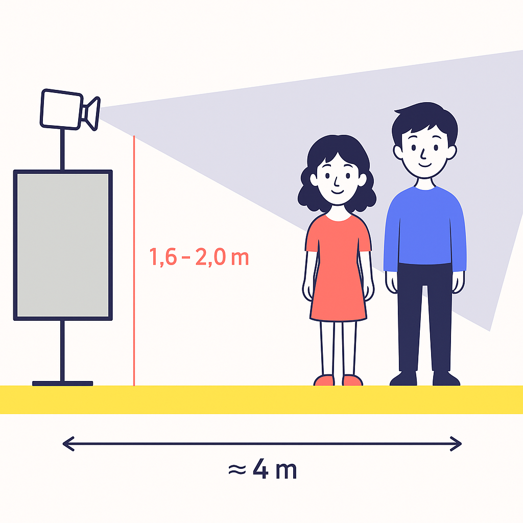
(See Graphic 3-A: Eye-Level Camera Placement for Signage and Kiosks) -
Center the camera horizontally relative to the display to capture symmetrical viewing zones.
-
Tilt slightly toward the audience when the display is elevated to improve facial visibility and proof-of-view precision.
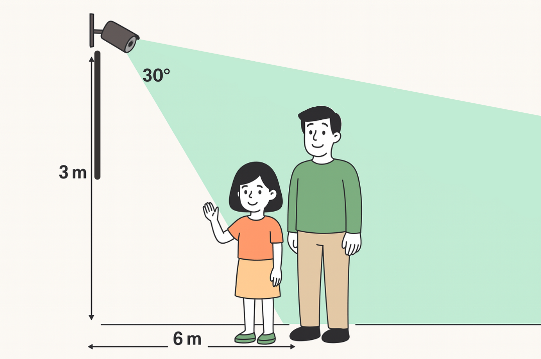
(See Graphic 3-B: High-Angle Wall / Ceiling Placement) -
Avoid obstructions such as staff, counters, or decorative elements that block the field of view.
These guidelines apply to both USB and IP (CCTV) cameras.
Graphic References
- Graphic 3-A — Eye-Level Placement Example
A front-facing USB camera mounted above a digital signage screen at ≈ 1.9 m captures viewers' faces and upper bodies within 4 m.
- Graphic 3-B — High-Angle Placement Example
An IP (CCTV) camera mounted at ≈ 3 m height on a wall at 30° tilt covers a 6 m viewing zone for traffic and occupancy counting.
The importance of defining the right detection area of interest
The Broox Vision Node includes built-in tools to define and visualize areas of interest directly within its
configuration interface. Please see more information here on
how to use the tool.
These tools allow the system to focus analytics only on the relevant portions of the camera feed — minimizing false
detections, improving tracking stability, and ensuring accurate proof-of-views (proof of play) and demographic
measurements.
Even with a correctly mounted camera, an incorrect detection area can reduce performance.
A well-defined area ensures that the system:
-
Focuses computation only where it matters.
-
Avoids counting people outside the intended interaction zone.
-
Maintains consistent calibration across multiple views.
Recommended Scenarios
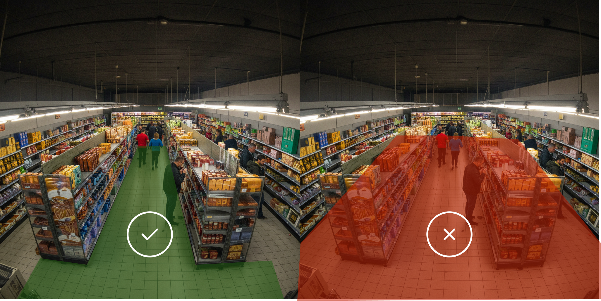
Passers-By Areas — Corridors and Halls
In wide corridors or transit zones, the objective is traffic counting.
Mount the camera at 2.5 – 3 m with a tilt below 30°.
Define a long, narrow detection band aligned with the walking direction, and ensure the floor is visible so the tracker
captures full-body movement without occlusion.
When the camera angle provides complete frontal visibility of faces, age and gender estimation can also be considered
reliable.
Retail Entrances
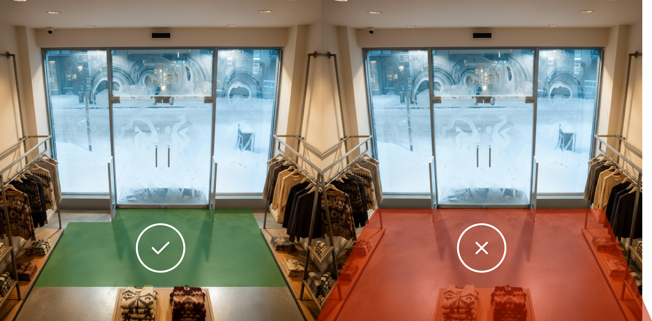
For entrances, focus on flow direction and occupancy tracking.
Mount the IP camera at 2.5 – 3 m, centered on the doorway.
Define a rectangular area spanning the door width and extending 1 – 2 m inside/outside the threshold.
Avoid obstacles such as displays or cash desks that may obstruct visibility.
If the entrance layout and lighting allow face frontal visibility toward the camera, age/gender analytics can also be
activated.
Digital Signage and Interactive Screens
For proof of views and age/gender analytics, place a USB camera at eye level (1.8 – 2.2 m) above or below the screen.
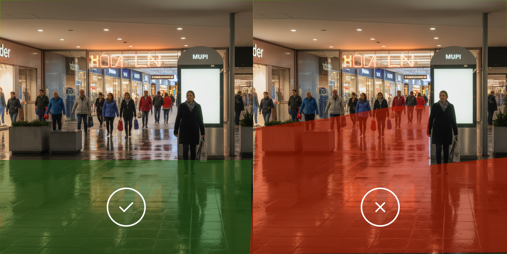
Define a frontal, trapezoid-shaped area that ensures the viewer’s floor contact area is visible, with no obstructions.
Best Practices for Area of Interest Definition
-
The floor must be visible in the camera view to anchor movement and position estimation.
-
Passers-by must not be occluded by furniture, counters, or decorative elements.
-
Individuals should be fully visible from head to feet to preserve pose and orientation accuracy.
-
Validate with live preview: Observe detection overlays while people move through the area to confirm visibility and scale.
-
Restrict area depth: Align it with the intended engagement zone to avoid background noise.